
11.92 10 Axis and Spindle Installation
10.4.4 Reference point approach
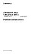
2nd case: Axis is at the reference point cam
Rather than accelerate to the reference speed, the axis accelerates immediately to the
reference point cutoff speed (MD 284*).
Axis is at reference point cam
2
Reference point pulse
MD 284*
2000 units
Speed
Path
3 4
Reference point cam Reference point
1
3rd case: Axis is behind the reference point cam
Since the signal state of the "Deceleration" signal is the same after the reference point as it
was before, the control assumes that the axis is still ahead of the reference point cam and
therefore accelerates to the reference approach speed (MD 296*), i.e. the axis travels at high
speed toward the limit switch (EMERGENCY STOP), as the software limit switches are not in
force prior to or during reference point approach.
Axis is behind reference point cam
Speed
MD 296*
Path
Reference point cam
Reference point pulse
Reference point
0
Limit switch
If referencing is repeated several times, the software limit switches are exceeded by the
following error if the cam is not reached. The automatic direction recognition function is used
to remedy this.
In order to circumvent the problems posed by case 3, it was necessary to integrate a complex
system of travel interlocks in the PLC. It was therefore decided that the SINUMERIK System
800 should provide an option which would solve the problem without additional PLC support
during reference point approach. This option is referred to as automatic reference point
approach, i.e. reference point approach with automatic direction recognition.
© Siemens AG 1992 All Rights Reserved 6FC5197- AA50 10–37
SINUMERIK 840C (IA)


 England
  Deutschland
  France
  Italia
  Polska
  United Kingdom
  Россия
  Nederland
  España
  Magyarország
  Sverige
  România
  Portugal
  Colombia
  Suomi
Suomi  New Zealand
  Česká republika
  Türkiye
  Danmark
  日本
日本