
6 NC Machine Data (NC MD), NC Setting Data (NC SD) 09.95
6.7.1 Axis-specific MD bits 2 (axial bits 2)
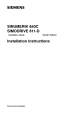
7 6 5 4 3 2 1 0
Bit No.
NC MD
1820*
Contour
monitoring
not active
Pulse
encoder
monitoring
on
No. of
encoder
pulses (611D)
2nd meas.
system (as
from SW 3)
Second meas.
system with
external zero
mark (as from
SW 3)
No. of
encoder
pulses (611D)
1st meas.
system (as
from SW 3)
First meas.
system with
external zero
mark (as from
SW 3)
Zero
monitoring
on
Setpoint
smoothing
on
Default value: 0000 0000
Bit 7 Bit 7=1 The dynamic contour monitoring function is switched off.
Bit 6 Pulse encoder monitoring on
Bit 6=1 Monitoring is carried out to determine how many directional changes have
occurred between two measuring clock pulses. If too many directional changes
are detected, alarm 140* is triggered (also see description of alarm 140*).
Bit 6=0 Monitoring switched off.
Bit 5 Digital drives only:
Bit 5=0 Number of encoder intervals between two reference marks of the second
measuring system is a multiple of 16
Bit 5=1 Number of encoder intervals between two reference marks of the second
measuring system is a multiple of 10
Bit 4 Digital drives only:
Bit 4=0 Second measuring system without external zero mark (BERO)
Bit 4=1 Second measuring system without external zero mark (BERO)
1)
Bit 3 Digital drives only:
Bit 3=0 Number of encoder intervals between two reference marks of the first
measuring system is a multiple of 16
Bit 3=1 Number of encoder intervals between two reference marks of the first
measuring system is a multiple of 10
Bit 2 Digital drives only:
Bit 2=0 First measuring system without external zero mark (BERO)
Bit 2=1 First measuring system with external zero mark (BERO)
1)
Bit 1 Zero monitoring on
Bit 1=1 Monitoring is performed to detect whether pulses have been lost between two
zero mark passes (do not use for distance-coded reference marks).
If so, alarm 144* is triggered (also see description of alarm 144*).
Bit 1=0 Monitoring switched off
Bit 0 Setpoint smoothing on
Bit 0=1 The setpoint smoothing filter parameterized in MD 1272* is switched on.
_______
1) Speed-related errors in referencing occur with reference point approach with external zero mark (BERO).
This is caused by the delay time of the optocoupler at the input.
To avoid such errors in referencing, the maximum velocity must be limited.
6–188 © Siemens AG 1992 All Rights Reserved 6FC5197- AA50
SINUMERIK 840C (IA)


 England
  Deutschland
  France
  Italia
  Polska
  United Kingdom
  Россия
  Nederland
  España
  Magyarország
  Sverige
  România
  Portugal
  Colombia
  Suomi
Suomi  New Zealand
  Česká republika
  Türkiye
  Danmark
  日本
日本