
Diagnostics and Troubleshooting - User Interface
Revision 5 HC900 Hybrid Controller Installation and User Guide 121
9/03
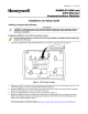
Table 26 - LED Indications on Ethernet Hub
LED LED State/Color Indicates Condition:
Green (On/Off)
Green (On/Off)
On while a message is being sent from the Main
CPU; otherwise Off.
On while the Main CPU is receiving a message.
Remains On as long as host is present; Off
when the host is removed from the link.
10Base-T port
(I/O Expansion –C50
CPU only)
XMT (upper LED)
LINK (lower LED)
NOTE: These LEDs indicate activity on the communication port, they are
controlled by hardware (PHY chip), not by software.
User Interface
Table 27 lists Controller Module diagnostic indications (Operator Interface messages, and Status LED) along with
causes of the indications, automatic control file actions, and suggested user actions.
Hazardous voltages exist in the equipment enclosure.
• Identify and avoid contact with voltage sources.
• Disconnect power before servicing. (More than one switch may be required to disconnect all power.)
Failure to comply with these instructions could result in death or serious injury.
Table 27 - Controller Module Diagnostics
Table 27 - Controller Module Diagnostics
OI Screen
Item
OI Screen
Item Value
Number of
LED
Strobes
Possible Cause Control File Action User Action
N/A N/A 1 RAM failed on power-
up.
Executes an infinite loop
that toggles the LED.
Communications and
control are disabled.
1. Cycle power
2. Replace CPU
3. Replace rack
N/A N/A 1 ROM failed on power-
up.
Executes an infinite loop
that toggles the LED.
Communications and
control are disabled.
1. Cycle power
2. Replace CPU
3. Replace rack
SYSTEM GOOD N/A N/A N/A N/A
FORCED
OUTPUT
2 A block has an output
that is forced.
None Remove force on
block output.


 England
  Deutschland
  France
  Italia
  Polska
  United Kingdom
  Россия
  Nederland
  España
  Magyarország
  Sverige
  România
  Portugal
  Colombia
  Suomi
Suomi  New Zealand
  Česká republika
  Türkiye
  Danmark
  日本
日本