
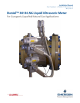
Daniel 3818 LNG Liquid Ultrasonic Meter Installation Manual List of Figures
3-9000-771 Rev A May 2012
List of Figures v
List of Figures
Figure 1-1 Daniel MeterLink download and registration ................................................................ 5
Figure 1-2 3818 LNG Meter with remote mount electronics and band shroud assembly................ 6
Figure 1-3 Daniel 3810 Series Liquid Ultrasonic Meter ATEX approval ......................................... 12
Figure 2-1 Daniel 3818 Liquid Ultrasonic Flow Meter assembly .................................................. 17
Figure 2-2 Piping recommendations unidirectional flow.............................................................. 19
Figure 2-3 Piping recommendations bidirectional flow................................................................ 19
Figure 2-4 Meter end flange with tapped flat-counterbore hole for hoist ring ............................ 23
Figure 2-5 Safety approved hoist ring and non-compliant eye bolt ............................................. 24
Figure 2-6 90 Degree angle between slings ................................................................................. 25
Figure 2-7 Incorrect sling attachment ......................................................................................... 26
Figure 2-8 Correct sling attachment with spreader bar ............................................................... 29
Figure 2-9 Incorrect sling attachment.......................................................................................... 30
Figure 2-10 Transducer cabling conduit......................................................................................... 32
Figure 3-1 Internal Transmitter Electronics Enclosure chassis ground .......................................... 36
Figure 3-2 External ground lug .................................................................................................... 37
Figure 3-3 CPU Module labeling and LED indicators ..................................................................... 42
Figure 3-4 PC to meter serial connection wiring ........................................................................ 46
Figure 3-5 CPU Module I/O connections...................................................................................... 47
Figure 3-6 CPU Module - Frequency/Digital inputs common ground ........................................... 51
Figure 3-7 CPU Module power source connections ..................................................................... 53
Figure 3-8 Transmitter electronic enclosure security latch .......................................................... 54
Figure 3-9 Transmitter Electronics Enclosure security seal installation ........................................ 55
Figure 3-10 Base Enclosure wire seal installation ........................................................................... 56
Figure 4-1 Daniel MeterLink - Meter Directory ............................................................................ 59
Figure 4-2 AMS Device Description search................................................................................... 62
Figure 4-3 AMS file download complete ...................................................................................... 63
Figure 4-4 AMS Device Manager ................................................................................................ 64
Figure 4-5 AMS Device Manager - Overview ............................................................................... 64
Figure 4-6 AMS Device Manager - Guided Setup ......................................................................... 65
Figure 4-7 AMS Device Manager - Zero Flow .............................................................................. 66
Figure 4-8 AMS Device Manager - Service Tools All Variables status indicators............................. 68
Figure 4-9 Display Meter K-Factors .............................................................................................. 68
Figure 4-10 AMS Device Manager - Configure Manual Setup.......................................................... 69


 England
  Deutschland
  France
  Italia
  Polska
  United Kingdom
  Россия
  Nederland
  España
  Magyarország
  Sverige
  România
  Portugal
  Colombia
  Suomi
Suomi  New Zealand
  Česká republika
  Türkiye
  Danmark
  日本
日本